Friday 27 November 2015

WHAT ARE THE APPLICATIONS AND ADVANTAGES OF BLDC MOTOR.?


 Also called brushless Permanent Magnet DC (BLDC) or synchronous DC motor
           Advantages :
o     High efficiency (up to 98%)
o      Variable speed
o      Silent operation
o      Reliable/long life time (no brushes)
o     High Power/ Size ratio
o     High torque at start-up
              Compressor (air conditioner, refrigerator)
              Appliances (refrigerator, vacuum cleaner*, food processor*)
              Industrial fan
      Automotive (fuel* and water*pumps, cooling fan*, climate control)
            Drawbacks:
             Overall system cost due to cost of electronic control
             FOR MORE DETAILS: Click Here

WHAT IS THE PRINCIPLE OF DC MACHINE...?


 A DC motor is a device for converting DC electrical energy into rotary (or linear) mechanical energy. This process can be reversed, as in a DC generator, to convert mechanical to electrical power. The working principle of the DC (and AC as well) generator is Faraday’s Law, which states that emf and electric current if the circuit is closed, is produced when a conductor cuts through magnetic force lines. The opposite of the law applies for the DC (and AC) motor. Motion is produced when a

 current carrying wire is put in a magnetic field.


FOR MORE DETAILS: CLICK HERE.. 

PV GRID-CONNECTED INVERTER


  • A full-bridge inverter topology with constant common-mode voltage (FB-CCV) has been derived and proposed in this article, two unidirectional freewheeling branches are added into the ac side of the FB-CCV, and the split structure of the proposed freewheeling branches does not lead itself to the reverse-recovery issues for the freewheeling power switches and as such super junction mosfets can be utilized without any efficiency penalty. 
  • The passive clamping branches consist of a capacitor divider and two Diodes, is added into the dc side of the FB-CCV, therefore, the Weakness of active damping branch has been overcome, and the Better clamping performance has been achieved in the freewheeling Period. 

FOR MORE DETAILS: CLICK HERE... 

Bridgeless converter based multiple output SMPS

         This paper deals with the development of a power-factor-correction (PFC) multiple output switched-mode power supply (SMPS) using a bridgeless buck–boost converter at the front end.


       Single-phase ac supply is fed to a pair of back-to-back-connected buck–boost converters to eliminate the diode bridge rectifier, which results in reduction of conduction losses and power quality improvement at the front end.
       
         The operation of the bridgeless buck–boost converter in discontinuous conduction mode ensures inherent PFC operation and reduces complexity in control. The performance of the proposed multiple-output SMPS is evaluated under varying input voltages and loads.

FOR MORE DETAILS   :  CLICK HERE....

WHAT IS COMMUTATOR..?

     
DC MACHINE :COMMUTATOR
  
  1.               The rotor has a ring-shaped laminated iron core with slots.
    ·     The commutator consists of insulated copper segments mounted on an insulated tube.
    ·        Two brushes are pressed to the commutator to permit current flow.
    ·    The brushes are placed in the neutral zone, where the magnetic field is close to zero, to reduce arcing
    ·     The commutator switches the current from one rotor coil to the adjacent coil The switching requires the interruption of the coil current.
    ·        The sudden interruption of an inductive current generates high voltages .
    ·        The high voltage produces flashover and arcing between the commutator segment and the brush.

FOR MORE DETAILS:CLICK HERE..

HPF RECTIFIER USING THE MODIFIED SEPIC CONVERTER

  • The theoretical and experimental analysis of a modified version of the SEPIC  dc–dc converter used as preregulator operating in discontinuous conduction mode (DCM) is presented .
  •  The proposed converter presents a low input current ripple operating in DCM, and the switch voltage is lower than the output voltage.


                                                            SEPIC CONVERTER


  • The switch voltage reduction increases the converter reliability and a low drain-to-source on-resistance (RDSon ) MOSFET can be used depending on the converter specification.
  •  Moreover, a digital control technique is applied to the proposed converter in order to reduce the third-harmonic input current distortion resultant of the operation in DCM. Finally, a 100-W prototype was developed operating with efficiency equal to 95.6%..


FOR MORE DETAILS:  CLICK HERE

AC/DC OFFLINE SINGLE-SWITCH LED DRIVERS WITHOUT ELECTROLYTIC CAPACITORS

Energy-efficient residential lighting such as household Light-Emitting Diode (LED) lamps with AC input require an AC/DC converter (or driver) with large output capacitance to minimize the low frequency LED current ripple. The energy storage capacitor used in the conventional AC/DC LED driver is usually an electrolytic capacitor due to its low cost and high energy density. However, the average lifetime of an electrolytic capacitor is at least 2 to 3 times less than that of a LED device. Hence, the potential lifetime of the LED lamp is significantly affected by the presence of the electrolytic capacitor in the driver circuit. In this article, 2 novel isolated single-switch AC/DC high power factor LED drivers without using any electrolytic capacitors are proposed. In the proposed circuits, the energy storage capacitor is moved to the rectifier side, with a three-winding transformer used to provide isolation; input power factor correction as well as to store and provide the required energy to the output. As a result, the energy storage capacitance is significantly reduced, which allows film capacitor to be used to replace the conventionally used electrolytic capacitors. 


FOR MORE DETAILS: CLICK HERE....

DC TO DC CONVERTER FOR DISTRIBUTED ENERGY SOURCES


  • This article presents high step-up DC to DC converter for low voltage sources like solar PV, fuel cells and battery banks. 
  • To achieve high voltage gain without la RGE duty cycle operation, combination of coupled inductor and switched capacitor voltage doublers cells are used. 
  • By incorporating active clamp circuit, voltage spike due to the leakage inductance of the coupled inductor is alleviated and ZVS turn ON of the main and auxiliary switch is obtained. 
  • Due to the use of MOSFETs of low voltage rating and soft turn ON of the switches, conduction loss and switching losses are reduced. This improves the efficiency and power density of the converter.


FOR MORE DETAILS: CLICK HERE

MULTILEVEL INVERTER WITH REDUCED NUMBER OF COMPONENTS

  • In this article, a new cascaded multilevel inverter is presented.
  •  For the proposed inverter, two different algorithms to determine the magnitude of dc voltage sources are proposed. 
  • Then, in order to generate maximum numbers of output voltage levels by using constant number of power switches and or dc voltage sources, several optimum structures of the proposed inverter are obtained.


  •  In comparison with the conventional cascaded multilevel inverters, the proposed inverter is able to generate high number of output voltage levels by using lower number of power electronic devices such as power switches, driver circuits, power diodes and dc voltage sources. 
  • In addition, the low amount of blocked voltage by switches is another advantage of the proposed inverter. 
  • The accuracy performance of the proposed inverter in generation the positive and negative voltage levels is verified through the experimental results on a 61- level inverter.

WHAT IS COMMUTATION..?

COMMUTATION:

In larger machines the commutation process would involve too much sparking, which causes brush wear, noxious gases (ozone) that promote corrosion, etc. In these cases it is common to use separate commutation interpoles. These are separate, usually narrow or seemingly vestigal pole pieces which carry armature current. They are arranged in such a way that the flux from the interpole drives current in the commutated coil in the proper direction. Remember that the coil being commutated is located physically between the active poles and the interpole is therefore in the right spot to influence commutation. The interpole is wound with armature current (it is in series with the main brushes). It is easy to see that the interpole must have a flux density proportional to the current to be commutated. Since the speed with which the coil must be commutated is proportional to rotational velocity and so is the voltage induced by the interpole, if the right 7 number of turns are put around the interpole, commutation can be made to be quite accurate.


for more details: CLICK HERE..

Basics of Offline UPS Systems


UPS Introduction:
                         The “Uninterruptable Power Supply” is also called as Standby Power Supply, since they stand by whilst the main power supply is working. These power supplies usually consists of inverters operating from DC storage source (like battery). In many applications like major computer installations, process control in chemical plants, hospital intensive care units continuous power supply is highly essential. In these applications, temporary power failure can cause a great inconvenience and economic losses.  The UPS plays an important role in these situations.
The following figure shows the configuration of an offline UPS system. It is also known as Line-Preferred UPS or Passive Standby. The Offline UPS System is the simplest form of back up power systems.

Operation:

§  The Offline UPS systems normally operate off-line and the load is normally powered by the utility line.
§  When the utility power levels goes beyond acceptable limits, or fails, the load is transferred from the utility line to the UPS. 
§  The actual transfer time is very fast, but the detection time somehow long and therefore the offline UPS is not as reliable as an online UPS.
Advantages, Disadvantages of Offline UPS System:
§  The major advantage of the off-line UPS systems is lower cost, smaller size and weight and higher efficiency. 
§  It has higher efficiency because most of the time the UPS system is offline and the load is powered by the utility.
§  The disadvantage of the Offline UPS system is that switching to the inverter is required when the load is most vulnerable (ie, upon failure of the normal power source)
§  These kind of systems provide no line conditioning or voltage regulation and provide only limited surge and spike protection. During the sustained low voltage periods(brownouts) the Offline UPS can inaccurately detect a blackout and prematurely switch onto battery.


WHAT IS THE BACK EMF..?

BACK EMF:


According to fundamental laws of nature, no energy conversion is possible until there is something to oppose the conversion. In case of generators this opposition is provided by magnetic drag, but in case of dc motors there is back emf.

When the armature of the motor is rotating, the conductors are also cutting the magnetic flux lines  and hence according to the faraday's law of electromagnetic induction, an emf induces in the armature conductors. The direction of this induced emf is such that it opposes the armature current (Ia) . The circuit diagram below illustrates the direction of the back emf and armature current. Magnitude of Back emf can be given by the emf equation of dc generator.


FOR MORE DETAILS: CLICK HERE...


What are the applications of Power Electronics System?

Electrical_Drive_Block_Diagram
It is astonishing to realise that there is hardly a home, office block, factory, car, sports hall, hospital or theatre without an application of power electronic equipment.
1. Aerospace
Space shuttle power supplies
Satellite power supplies
Aircraft power system
2. Commercial:-
Advertising, heating, air-conditioning power supplies, computer, office equipment, elevators, light dimmer, uninterruptible power supplies, central refrigeration.
3. Industrial:-
Arc and Industrial furnaces, blowers and fans, pumps and compressors, industrial lasers, transformer tap changers, rolling mills, textile mills, excavators, cement mills, welding
4. Residential:-
Air conditioning, cooking, lighting, refrigerators, electric-door openers, dryers, fans, personal computers, vacuum cleaners, washing machine, food mixers
5. Telecommunication:-
Battery chargers, power supplies
6. Transportation:-
Battery chargers, traction control of electric vehicles, electric locomotives, street cars, trolley buses, subways, automotive electronics.
7. Utility systems:-
High voltage DC Transmission, Excitation systems, VAR compensation, Static circuit breakers, fans and boiler feed pumps, supplementary energy systems(solar, wind)

CLASSIFICATIONS OF DC MACHINES :(DC MOTORS AND DC GENERATORS)

CLASSIFICATIONS OF DC MACHINES:

Each DC machine can act as a generator or a motor. Hence, this classification is valid for both: generators and DC motors. DC machines are usually classified on the basis of their field excitation method. This makes two broad categories of dc machines; (i) Separately excited and (ii) Self-excited.
classification of dc machines / dc generators / dc motors


  • Separately excited: In separately excited dc machines, field winding is supplied from a separate power source. That is, field winding is electrically separated from the armature circuit. This type of dc machines is not commonly used.
  • Self excited: In this type, field winding and armature winding are interconnected in various ways to achieve wide range of performance characteristics. Depending on that, self-excited machines can be further classified as –
    • Series wound – In this type, field winding is connected in series with the armature winding. Therefore, the field winding carries whole load current (armature current). That is why series winding is designed with few turns of thick wire and the resistance is kept very low (about 0.5 Ohm).
    • Shunt wound – Here, field winding is connected in parallel with the armature winding. Shunt winding is made with large number of turns and the resistance is kept very high (about 100 Ohm). It takes only small current which is less than 5% of the rated armature current.
    • Compound wound – In this type, there are two sets of field winding. One is connected in series and the other is connected in parallel with the armature winding. Compound wound machines are further divided as -
      • Short shunt – field winding is connected in parallel with only the armature winding
      • Long shunt – field winding is connected in parallel with the combination of series field winding and armature winding.
    • FOR MORE DETAILS: CLICK HERE..


Introdution about Auto Transformer

auto transformer

  An auto transformer is an electrical transformer having only one winding. The winding has at least three terminals which is explained in the construction details below.


Some of the advantages of auto-transformer are that,

  • they are smaller in size, 
  • cheap in cost, 
  • low leakage reactance,
  • increased kVA rating, 
  • low exciting current etc. 
An example of application of auto transformer is, using an US electrical equipment rated for 115 V supply (they use 115 V as standard) with higher Indian voltages. Another example could be in starting method of three phase induction motors

Construction Of Auto Transformer

 An auto transformer consists of a single copper wire, which is common in both primary as well as secondary circuit. The copper wire is wound a laminated silicon steel core, with at least three tappings taken out. Secondary and primary circuit share the same neutral point of the winding. The construction is well explained in the diagram. Variable turns ratio at secondary can be obtained by the tappings of the winding (as shown in the figure), or by providing a smooth sliding brush over the winding. Primary terminals are fixed.
Thus, in an auto transformer, you may say, primary and secondary windings are connected magnetically as well as electrically.

Working Of Auto Transformer

As I have described just above, an auto transformer has only one winding which is shared by both primary and secondary circuit, where number of turns shared by secondary are variable. EMF induced in the winding is proportional to the number of turns. Therefore, the secondary voltage can be varied by just varying secondary number of turns.
As winding is common in both circuits, most of the energy is transferred by means of electrical conduction and a small part is transferred through induction.


The considerable disadvantages of an auto transformer are,

  • any undesirable condition at primary will affect the equipment at secondary (as windings are not electrically isolated),
  • due to low impedance of auto transformer, secondary short circuit currents are very high,
  • harmonics generated in the connected equipment will be passed to the supply.

WHAT IS THE WORKING PRINCIPLE OF DC MOTOR..?

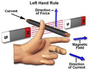
A motor is an electrical machine which converts electrical energy into mechanical energy. The principle of working of a DC motor is that "whenever a current carrying conductor is placed in a magnetic field, it experiences a mechanical force". The direction of this force is given by fleming left hand's rule and it's magnitude is given by F = BIL. Where, B = magnetic flux density,
                            I = current
                            L = length of the conductor within the magnetic field.


FLEMING LEFT HAND'S RULE: If we stretch the first finger, second finger and thumb of our left hand to be perpendicular to each other AND direction of magnetic field is represented by the first finger, direction of the current is represented by second finger then the thumb represents the direction of the force experienced by the current carrying conductor.

Above animation helps in understanding the working principle of a DC motor. When armature winding are connected to a DC supply, current sets up in the winding. Magnetic field may be provided by field winding (electromagnetism) or by using permanent magnets. In this case, current carrying armature conductors experience force due to the magnetic field, according to the principle stated above.

Commutator is made segmented to achieve unidirectional torque. Otherwise, the direction of force would have reversed every time when the direction of movement of conductor is reversed the magnetic field.


FOR MORE DETAILS: CLICK HERE..


Difference between AC And DC Current

Electricity flows in two ways – Alternating Current or Direct Current . The difference between the two is the way the electron flows.
DC and AC current

Owing to Thomas Edison - DC power was born by creating a magnetic field near a wire, which caused the electrons to flow in a single direction, from negative to positive.

Nikola Tesla came up with AC power because a it was a safer way to transmit power over large city distances. Instead of using a steady magnet, he used a rotating magnet. So as the magnets position changed so did the flow of electrons.

Difference Between AC And DC

Alternating CurrentDirect Current
The electrons keep on switching their path. AC current can travel over longer distances.The electrons flow in one direction. DC current cannot travel far otherwise it would lose energy.
Rotating magnetismSteady magnetism
Frequency of an AC current is usually 50Hz or 60Hz. i.e. current is varying over time.Frequency of DC current is zero. i.e. Current is constant over a period of time.
Used popularly for many applications like fans, air conditioners. Regular supply to homes is AC.Used mostly where mobility of electric power is essential. e.g. cell phones, batteries in vehicles etc.

What Are Diodes, GTO And Transistors?


Diodes: It is a semiconductor device with two terminals that allows flow of current in one direction. It has low resistance to current in one direction and a very high resistance on the other. It is a vacuum tube that has two electrodes – a plate (anode) and a heated cathode.
vacuum tube diode

A semiconductor diode was the first semiconductor electronic devices. Most diodes are made of silicon, while selenium or germanium is also used sometimes. Because a diode allows electric current to pass one way but not the other, it is used as a rectifier to convert AC to DC current.

Diodes are also used as signal limiters, voltage regulators, switches, signal modulators, signal mixers etc.

GTO thyristorGTO: Gate Turn-Off Thyristor, is a high powered semi-conductor device. It differs from a normal Thyristor. Unlike them a GTO has a fully controllable switch that can be tuned off and on by a third lead i.e. the Gate lead.

A normal thyristor does not have a fully controllable switch i.e., which can be turned on and off at will. Once it has been turned on or fired, it remains turned on till a turn off state occurs. Which could be anything like a reverse voltage or if the current flowing falls below a certain threshold value.

A GTO can be turned on by a gate signal and can be turned off by one which has negative polarity.

transistor
Transistors: This is semi-conductor device that is used for amplifying and switching electronic signals and power. A transistor has 3 terminals. When voltage or current is applied to one pair of terminal it changes through the other pair. The output power could be higher than the input, a transistor can amplify signals. Most of the transistors are found in integrated circuits.

The three leads that the transistor has are – Base, collector and Emitter. One of the most used transistors is MOSFET.

MOSFET
MOSFET: It stand for Metal Oxide Semiconductor Field Effect Transistor. This is a type of transistors that is used for amplifying or switching electronic signals. Though a MOSFET is a 4 terminal device – Source, Gate, Drain and Body. But as the Body Terminal and the Source Terminal are often connected to each other internally, therefore only three terminals appear in electrical diagrams. MOSFET is one of the most common transistors in both digital and analog circuits.